Case studies
Set up a shelf
Description
A ROC-E equipped with a Picker module (ROC-EP) can move a shelf equipped with the hooking system.
To move a shelf, the robot needs:
a specific position for picking up the shelf,
a specific position for placing the shelf.
The specific position for placing the shelf must be in close proximity to a marker so that the robot can place the shelf accurately.
When placing the shelf, the robot will first check that the space required for the shelf is free.
Configuration
Position for shelf mounting
Place the shelf where it needs to be picked up.
Place the robot under the shelf (the robot's position does not need to be very precise; the robot will automatically reposition itself in the correct place when picking up the shelf, based on its actual position).
On the robot screen:
Go to the
Configurationsection by clicking on the button at the bottom right and enter the access code.Go to the
Mapsection by clicking on the dedicated button.Click on the
+button to add a new item.Click on the
Add new shelf positionbutton.Then modify the new position created;
Customize the name, icon, and color of the position.
Enter the dimensions of the shelf (width, depth, height, feet width and weight).
Configure the height of the lift; this height will be the maximum height to which the lift can rise, and the lift will stop automatically when it detects contact with the shelf; this height must therefore be slightly higher than the position when contact is made.
Click on the
Lift heightbutton.Click on the arrows to adjust the height of the lift; the shelf should be slightly raised.
Click on the
Use this positionbutton.
Position for shelf unload
Place a marker near the placement location. This marker must be visible to the robot as it approaches and once it is in position.
Place the robot at the desired location for placing the shelf. This position must be precise.
On the robot screen:
Go to the
Configurationsection by clicking on the button at the bottom right and enter the access code.Go to the
Mapsection by clicking on the dedicated button.Click on the
+button to add a new element.Click on the
Add new docked positionbutton.Then modify the new position created; customize the name, icon, and color of the position.
Set up a picking station
Description
A ROC-E equipped with a Picker module (ROC-EP) can automatically pick up and drop off crates at picking stations.
In order to pick up or drop off a crate at a picking station, the robot needs a specific position for the picking station.
When dropping off, the robot will first check that there is no crate already present at the picking station.
Configuration
Place the picking station at the desired location for picking up or dropping off crates.
Place the robot precisely under the picking station (the robot will move to this exact position each time).
On the robot screen:
Go to the
Configurationsection by clicking on the button at the bottom right and enter the access code.Go to the
Mapsection by clicking on the dedicated button.Click on the
+button to add a new item.Click on the
Add new docked posebutton.Then modify the newly created pose;
Customize the name, icon, and color of the position.
Select
Pickingfrom theStation Typeoptions.Enter the dimensions of the crate (width, depth, height of the robot + crate, and weight).
Configure the height of the lift.
Click on the
Lift Heightbutton.Click on the arrows to adjust the height of the lift; the box must be raised 1 cm above the station.
Click on the
Use this positionbutton.
Repeat this configuration for all picking stations.
Configure door opening
Description
Using a LoRa controller, a robot can control the opening of automatic doors.
To control an automatic door, the robot needs:
a custom area to activate the door opening in one direction,
a custom area to activate the door opening in the other direction.
If the automatic door is equipped with a presence detector to open automatically in one direction of passage, the custom area will not be necessary.
A LoRa controller can control up to two nearby doors.
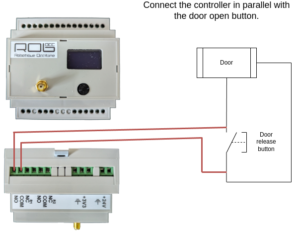
Installing the LoRa controller
Connection
Configuration
Refer to the documentation for the LoRa controller to configure the pulse duration to be used to open the door.
Generally, a 200 ms pulse is enough to open automatic doors.
Test
Consult the documentation for the LoRa controller to test the configuration and verify that the door opens.
Preparation of areas
As indicated in the introduction, it is necessary to define areas to control the opening of automatic doors.
The principle is as follows: if the robot needs to pass through the automatic door, it will trigger the opening command as soon as it enters the area.
It is therefore necessary to create an area “in front of” and “behind” the door to trigger the command.
The size of the area depends on the speed at which the door opens. If a door is slow, a large area will be set up to trigger the opening as soon as possible and facilitate the robot's navigation.
To add an area to the map:
On the robot screen:
Go to the
Configurationsection by clicking on the button at the bottom right and enter the access code.Click on the
Advanced Settingsmenu.Log in if necessary.
Click on the
Mapmenu.Click on the configuration icon in the menu on the left.
Click on the blue icon for custom areas.
Draw the desired area on the map.
Change the name in the left panel to make it easier to find the area later.
Configuration
Add the LoRa controller
The first step in the configuration process is to add the LoRa controller in the system.
On the robot screen:
Go to the
Configurationsection by clicking on the button at the bottom right and enter the access code.Click on the
LoRa Controllersmenu.Click on the
Add a LoRa controllerbutton.Enter the controller ID (displayed on the controller screen).
Enter a name (e.g., Door Opening).
Click on the
Addbutton.
Configuring custom commands
The second step of the configuration process consists of configuring the robot to send an open command when it needs to go through the door.
On the robot screen:
Go to the
Configurationsection by clicking on the button at the bottom right and enter the access code.Click on the
Custom Commandsmenu.Click on the
Add Custom Commandbutton.Enter a name (e.g., Open door to enter).
Select the command trigger zone (zone “in front of” or “behind” the door).
Select all targeted positions where the robot needs to open the door. You can activate the
All exceptswitch at the top so that you only have to select the positions that are not concerned.Select
On enterandIn the area.Select the controller you created earlier.
For the command, select
Relay 1 > Pulse(or relay 2 if the door has been connected to relay 2).Click on
Add.
Repeat this configuration to open the door in the other direction of navigation.
Set up a waiting point
Description
In the case of a fleet of robots, several robots may become stuck in certain situations, such as when there is a narrow corridor with no alternative route.
In these cases, it may be useful to set up waiting points so that one robot can clear the way for the others.
It may also be useful to set up a waiting point in cases where an alternative route exists but using it would result in too much time being lost.
To set up a waiting point, the robot needs:
a destination (the robot will only go to the waiting point if it is heading towards the destination, which allows for waiting points on either side of the corridor depending on the robot's movement),
a waiting position,
the area to be cleared.
If the robot fails to move into the area to be cleared (for example, if another robot is present in the opposite direction), the robot will automatically go to the waiting position.
The robot will automatically restart after x minutes (x can be configured in the delay settings) or if another robot indicates that it has just left the area.
Preparation of areas
Area to be cleared
On the robot screen:
Go to the
Configurationsection by clicking on the button at the bottom right and enter the access code.Click on the
Advanced Settingsmenu.Log in if necessary.
Click on the
Mapmenu.Click on the configuration icon in the menu on the left.
Click on the blue icon for custom areas.
Draw the desired area on the map.
Change the name in the left panel to make it easier to find the area later.
Waiting position
On the robot screen:
Go to the
Configurationsection by clicking on the button at the bottom right and enter the access code.Click on the
Mapmenu.Click on the green
+button.Click on the
Add new saved posebutton.Select the newly created pose.
Click on the pencil button to edit it.
Change the name to make it easier to find the position later.
Configuration
Once the area and the waiting position have been created;
On the robot screen;
Go to the
Configurationsection by clicking on the button at the bottom right and enter the access code.Go to the
Waiting Posessection by clicking on the dedicated button.Click on the
+ Add a waiting posebutton.Select the destination; this waiting pose will only be used if the robot is heading towards this destination.
Select the previously created waiting pose.
Select the previously created area.
Set up predefined messages
Description
In some cases, it may be useful for an operator to leave a message for the operator at the station where the robot is sent.
Our solution allows you to configure predefined messages that the operator can select to be displayed when the robot arrives at its destination.
For example, the robot can be used to send products to the control department, and it may be useful for the operator to specify whether it is a first in a series or a random sample.
Configuration
On the robot screen:
Go to the
Configurationsection by clicking on the button at the bottom right and enter the access code.Go to the
Predefined messagessection by clicking on the dedicated button.Add one or more messages by clicking on the
+ Add messagebutton.Enter your message
Add the message
Once a message has been added, it can be modified or deleted using the dedicated buttons.
Usage
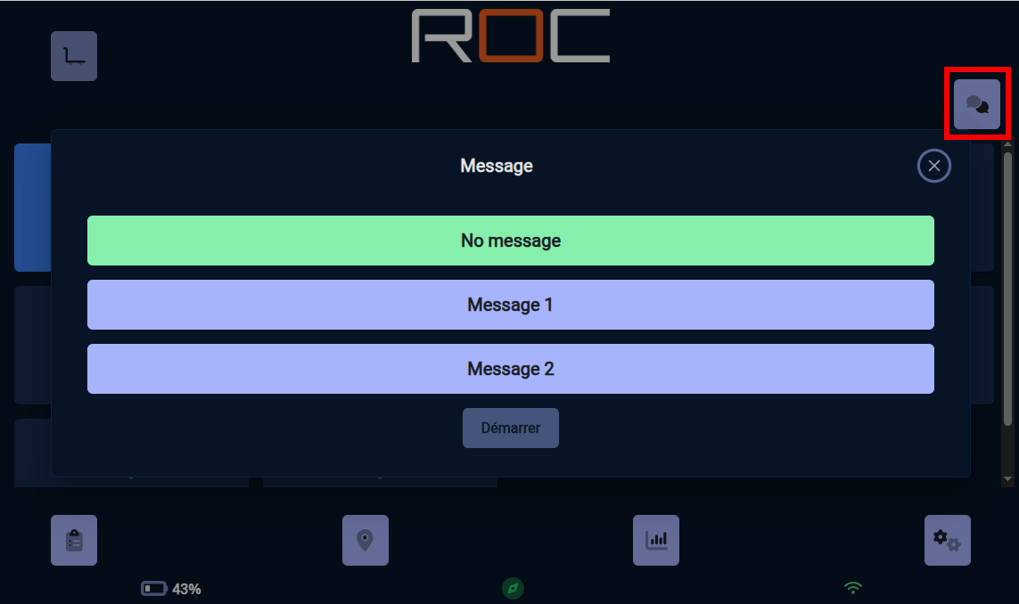
Once one or more predefined messages have been configured, the user will have access to new buttons to indicate a message;
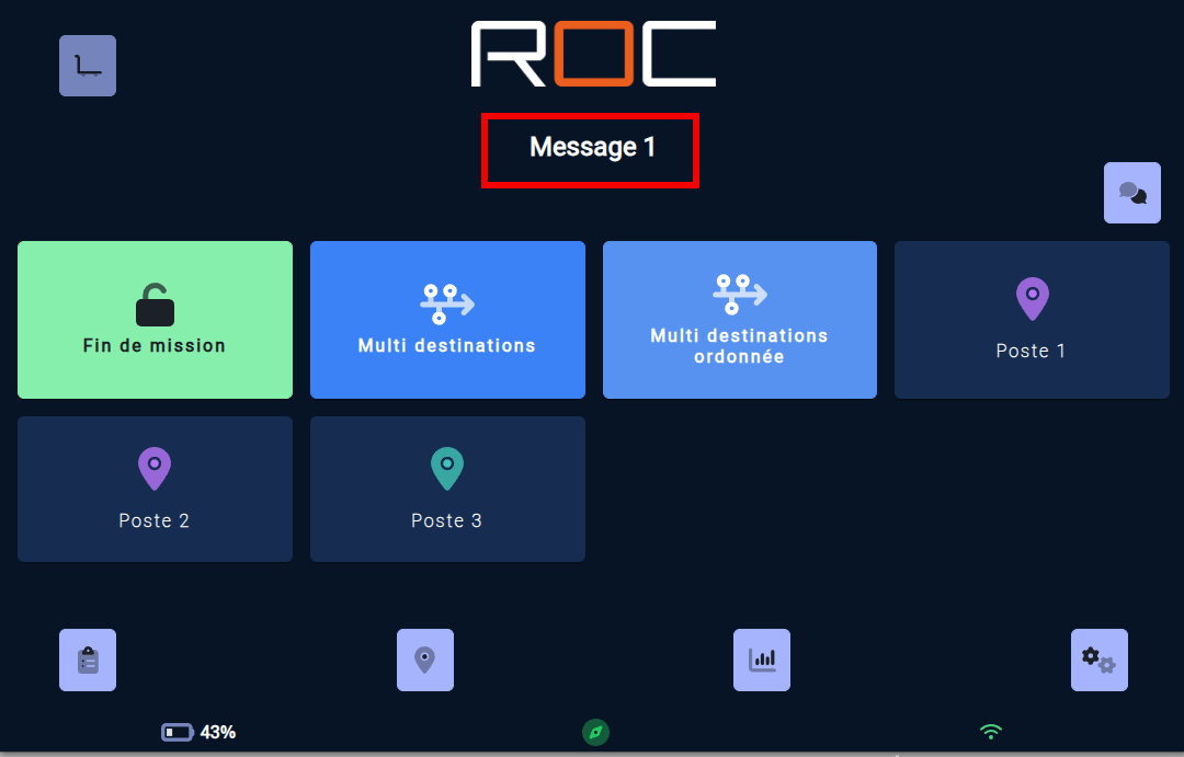
Main page; a button at the top right allows the user to select the message for the next mission. By clicking on the button, the user can select the message from the list of existing messages.
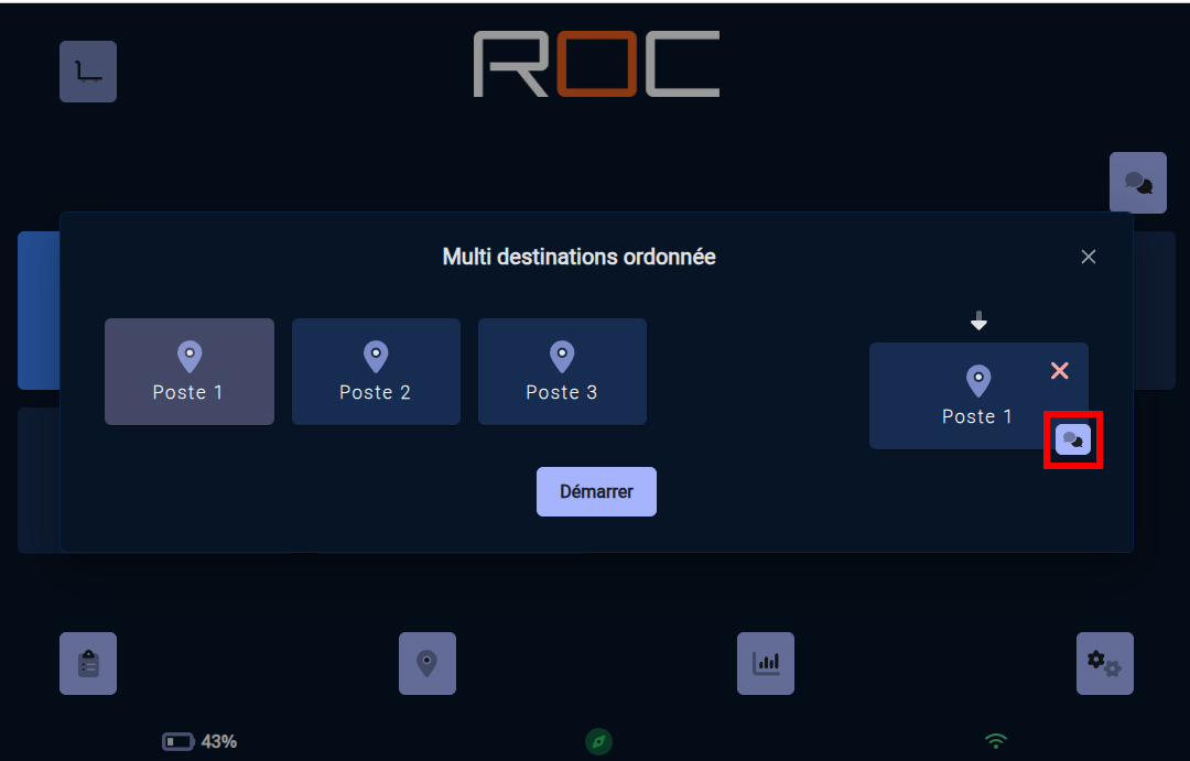
Multiple destinations and ordered multiple destinations; once a destination has been selected, a button allows you to select the message to be displayed when the robot reaches the selected destination.
The robot will automatically display the predefined message(s) at the appropriate time.
Synchronize robots and manager
Description
The robots in a fleet and the manager need to be synchronized to use the same map and the same configuration.
It is therefore necessary to update the equipment once a modification has been made to one device (robot or manager).
For simple modifications, it may be quicker to reconfigure each device (for example, to add a button).
The potential risk is that one device will not have the same configuration as the others (for example, a robot may not recognize the configuration of a button and therefore be unable to perform that task).
For more complex modifications, the simplest and most reliable method is to export the configuration of the device where the modification was made, then import it onto the other devices.
Export
Connect with a phone, tablet, or PC to the device's WiFi hotspot (robot or manager).
You will find the WiFi network password on the memo sheet provided with the device (if you have not changed the password).
Once connected to the Wi-Fi, open a web browser and go to: http://10.46.0.254 Log in with the username and password provided on the memo sheet of the robot (if you have not changed the username or password).
Go to the
Configurationsection by clicking on the button at the bottom right.Go to the
Import/Exportsection by clicking on the dedicated button.Click on the
Exportbutton to download the configuration file (your browser may ask you to confirm).
Import
Once the export has been downloaded, connect with the same device (phone, tablet, or PC) to the Wi-Fi hotspot of the other devices (robot and manager). You will find the Wi-Fi network password provided on the memo sheet of the device (if you have not changed the password).
Once connected to the Wi-Fi, open a web browser and go to the address: http://10.46.0.254 Log in with the username and password indicated on the memo sheet provided with the robot (if you have not changed the username or password).
Go to the
Configurationsection by clicking on the button at the bottom right.Go to the
Import/Exportsection by clicking on the dedicated button.Click on the
Importbutton and select the file you downloaded earlier.In the case of robots, you may be asked to select the default charging station.
My robot isn't moving anymore. Why?
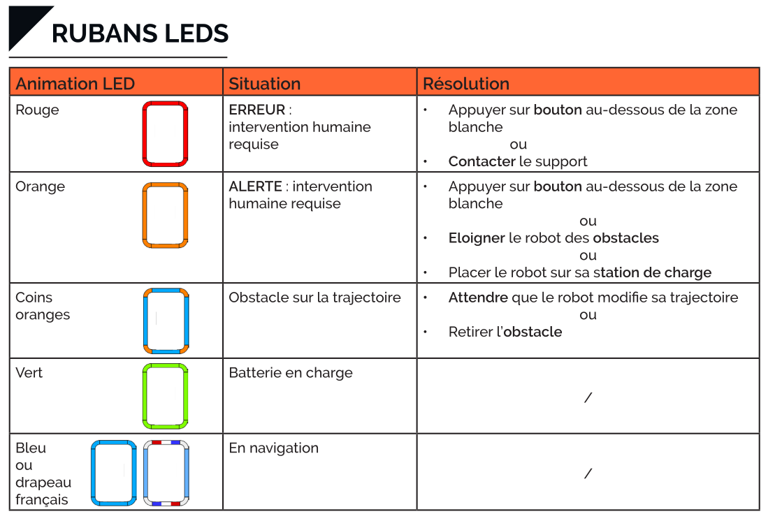
In certain situations, the robot may stop moving or stop during a movement. To determine the cause, look at the colors of the LEDs on the robot:
The LEDs are red; the robot is in HIR (Human Intervention Required) mode, and the robot's screen displays the procedure for unblocking the robot.
The LED corners are orange during movement: the robot's sensors have detected an obstacle blocking its movement.
All LEDs are off; the robot has no battery power left; move the robot to its charging station to recharge it.
If the LEDs are not in one of the above states,
Check that a movement command has been sent to the robot.
The robot cannot find a path to move to its destination;
Clear the space around the robot or move it to a free area.
Check that the destination saved on the map is not too close to a wall or obstacle.
My robot is jerking in some places, what should I do?
Description
In certain situations, it may appear as though the robot is avoiding “ghosts” obstacles; the LED corners light up orange and the robot goes around an apparently empty area.
This behavior is usually due to a false positive detection by the 3D cameras and/or ultrasonic sensors.
Configuration
To get around this problem, you need to create a custom area on the map where the robot shows this behavior.
Once the area has been created, you can:
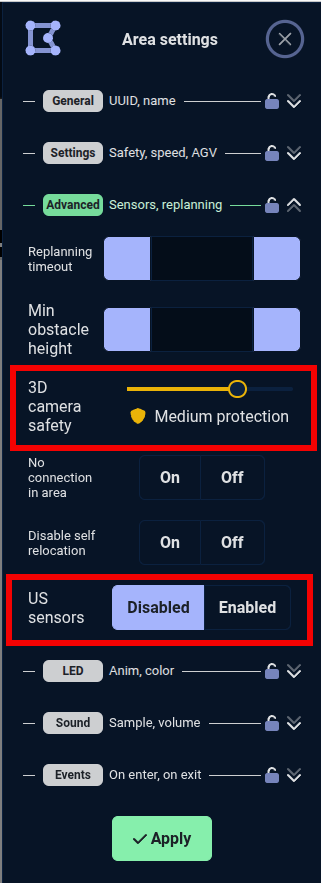
Reduce the sensitivity of the cameras, thereby reducing false positives.
Disable the ultrasonic sensors. Warning! The ultrasonic sensors are the only sensors on the robot that can detect glass. These sensors must not be disabled near glass doors.
My robot is lost, what should I do?
Description
In certain situations, the robot may become lost (it thinks it is in one location on its map but is physically in another location) or think that it is lost.
The robot can generally become lost in a highly changeable environment where it no longer has any reliable reference points on its map.
It may think it is lost if someone moves it into a forbidden area.
Relocate
In front of the robot, hold down the freewheel button; the screen will display the site map with the robot's position.
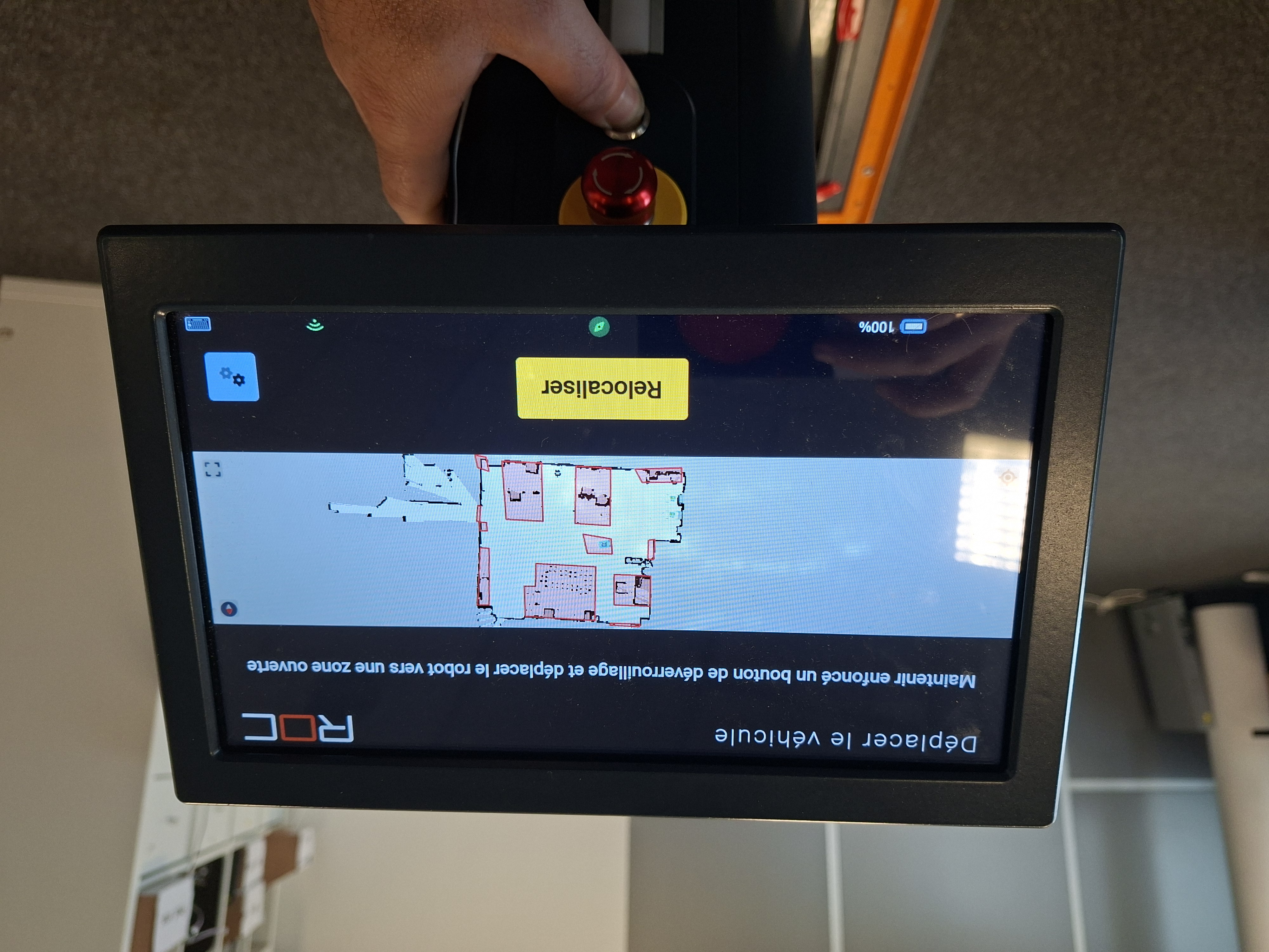
If the robot's position on the map matches its actual position, the robot is not lost. Move it to an open area outside of a forbidden area.
If the robot's position on the map does not correspond to its actual position, the robot is lost and must be relocated.
To relocate the robot, move it in front of a marker (e.g., a charging station). Once the robot has stopped in front of the marker, it will automatically relocate itself and resume its mission.
Configuration
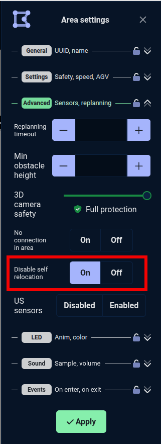
If the robot tends to repeatedly get lost in a particular area, it is possible to create a custom area in which the robot will be prohibited from dynamically relocating itself; the robot will evaluate its position based on its movements without attempting to relocate itself in relation to its map.
Create a custom area
Set the
Disable self relocationoption toON
My robot is having trouble entering an area. What should I do?
Description
In some cases, the robot may encounter difficulties when making a sharp turn or entering a room, for example.
In this case, it is possible to “force” the path that the robot will take to make it easier for it to pass.
Configuration
You can “force” the path that the robot will take to make it easier for it to pass by adding forbidden areas.
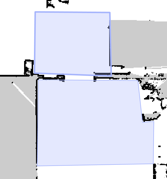
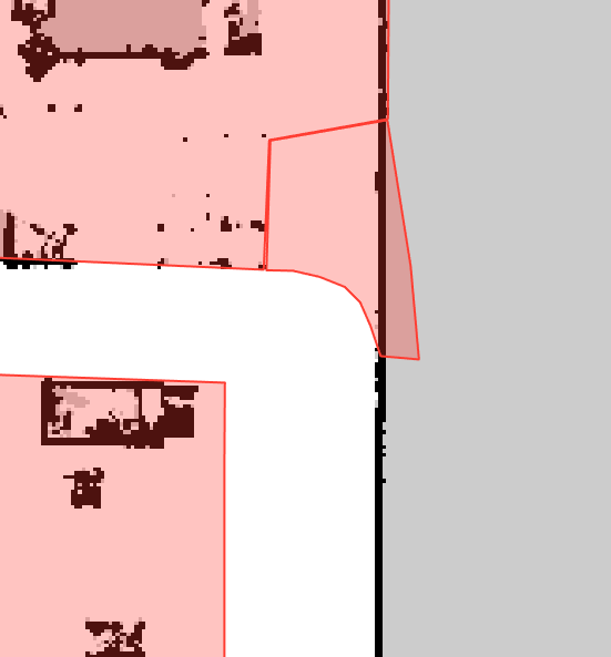
Turns
To “force” the robot to take a turn more smoothly, adding a forbidden area as shown below may be useful:
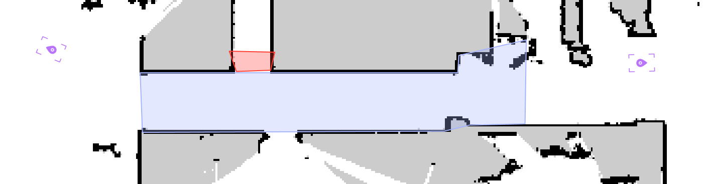
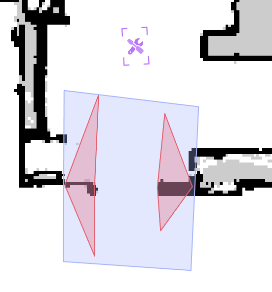
Doors
To “force” the robot to pass through a door more easily, adding two forbidden areas as shown below may be useful:
One-way routes
Description
In some locations, traffic rules are in place (such as one-way routes) and must also apply to AIVs.
Our solution allows you to configure these routes on the robot's map and thus apply traffic rules to the robot.
Please note: routes cannot be configured on only part of the map; if a route is required on part of the map, the entire map must consist of routes.
Configuration
Refer to the Noeme documentation, section Traffic routes.
Add an item with an identical marker already present on the map
Description
Markers are used for several purposes:
Precise location for robot positioning (charging station, picking station, etc.).
Automatic relocation of the robot when the freewheel button is pressed.
It is possible to use multiple markers with the same code on the same site.
The problem is that when adding the second marker, if you move the robot using the freewheel button, the robot will relocate itself to the new marker, thinking it is in front of the marker already present on the map.
Tip
The easiest way to add a marker with the same code as another marker already on the site is to:
Hide the new marker using a sheet of paper or something similar.
Move the robot to the desired location.
Remove the sheet of paper or similar to make the marker visible.
Add this new marker to the map.