Map
This page allows you to configure the vehicle's active map and modify its movement, avoidance etc. behavior.
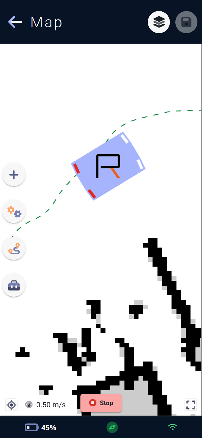
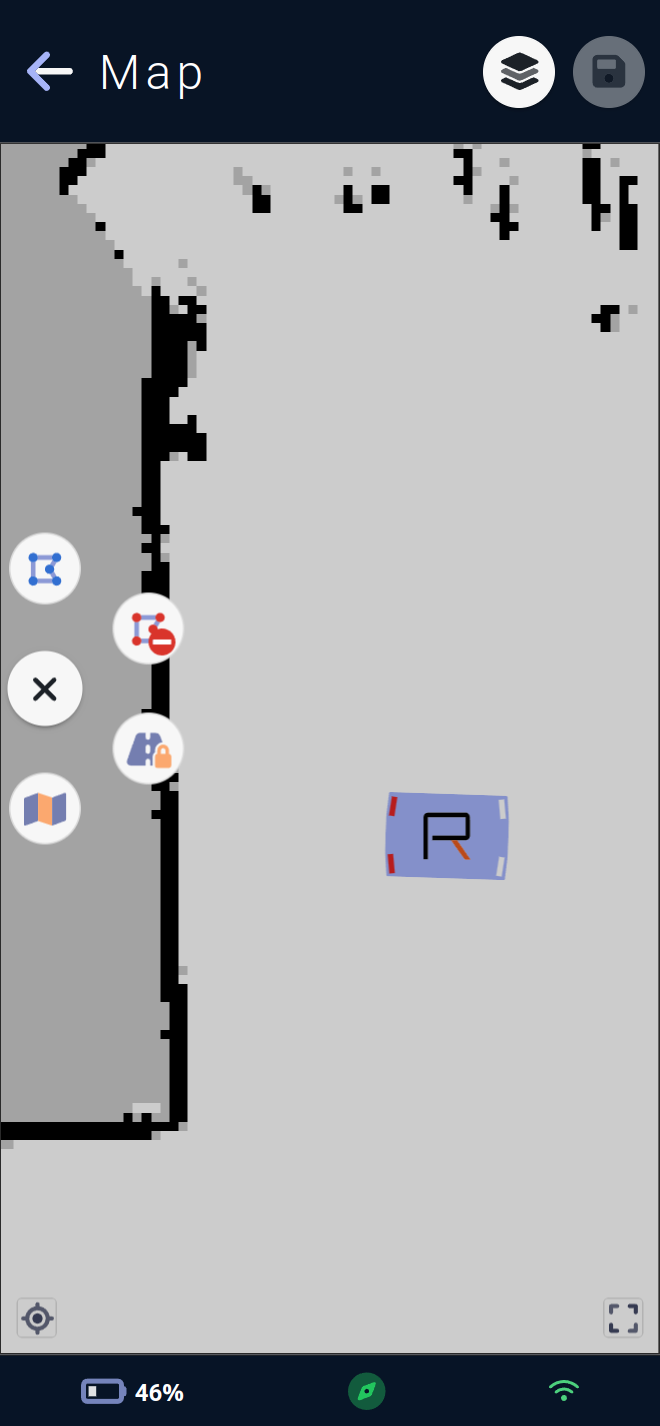
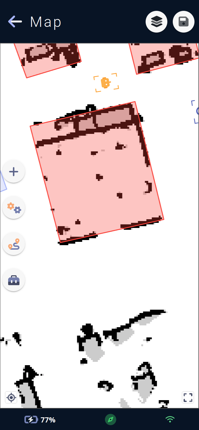
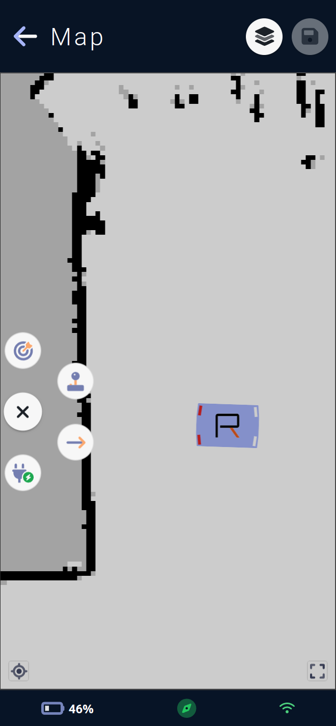
The active map is visible in the background of the page, with the white surface representing the exploitable surface for the vehicle, and the black surfaces representing the walls detected during the mapping stage (see ## Creating a new map). Surfaces in grey are unknown (often behind a wall or obstacle, the vehicle was unable to determine what was behind it).
The vehicle's current speed is shown at the bottom left of the map. For better visibility, the speed bubble will not be displayed if the vehicle is stationary.
The vehicle is represented on its map by a blue rectangle, with the Rob'Occ logo inside, and small white and red bars simulating car headlights to indicate the vehicle's current orientation. White bars indicate front and red bars indicate rear.
The navigation path is displayed in green and in motion when the vehicle is on a movement mission. This is a theoretical path, which the vehicle may follow to a greater or lesser extent depending on the environment or configuration.
The map's save button is located at the top right, and will turn green if map modifications have not yet been saved on the vehicle. It is not possible to save the map when the vehicle is on a move mission.
The layers menu is also located at the top right, next to the save button, and lets you show or hide certain layers or map elements, as well as select a map element.
Four other map action menus are available in the center left of the map:
The add menu for points of interest (charging station, saved and docked poses).
The configuration menu lets you add forbidden and custom areas, configure the vehicle's overall behavior on the map, and set up traffic routes.
The move menu allows the vehicle to move: straight segments, to its charging station, by clicking on the map, or to open a virtual joystick for teleoperation.
The toolbox menu contains advanced map-editing tools such as the eraser, as well as vehicle-location tools for manually locating the vehicle on the map or asking it to perform a
relocation.
In addition, elements drawn on the map are selectable when selection is active, and a menu corresponding to the actions available (delete, edit, translate etc.) on this element appears around the element's center.
A confirmation popup will be displayed if the page is exited and no changes have been saved.
Menus
Add Menu
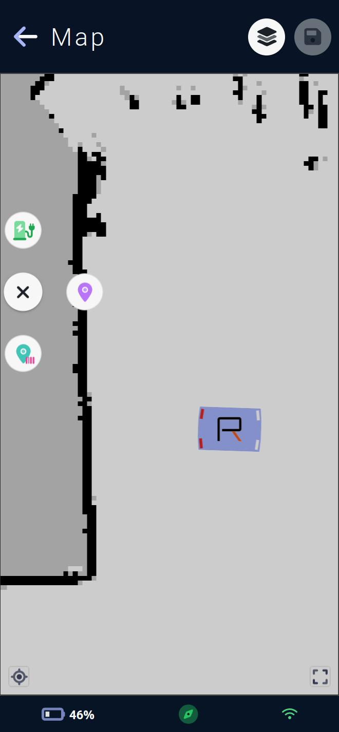
This menu lets you add three types of element to the map.
The charging station icon with its 🔌 plug starts the process of adding a
charging station.The map marker icon initiates the process of adding a
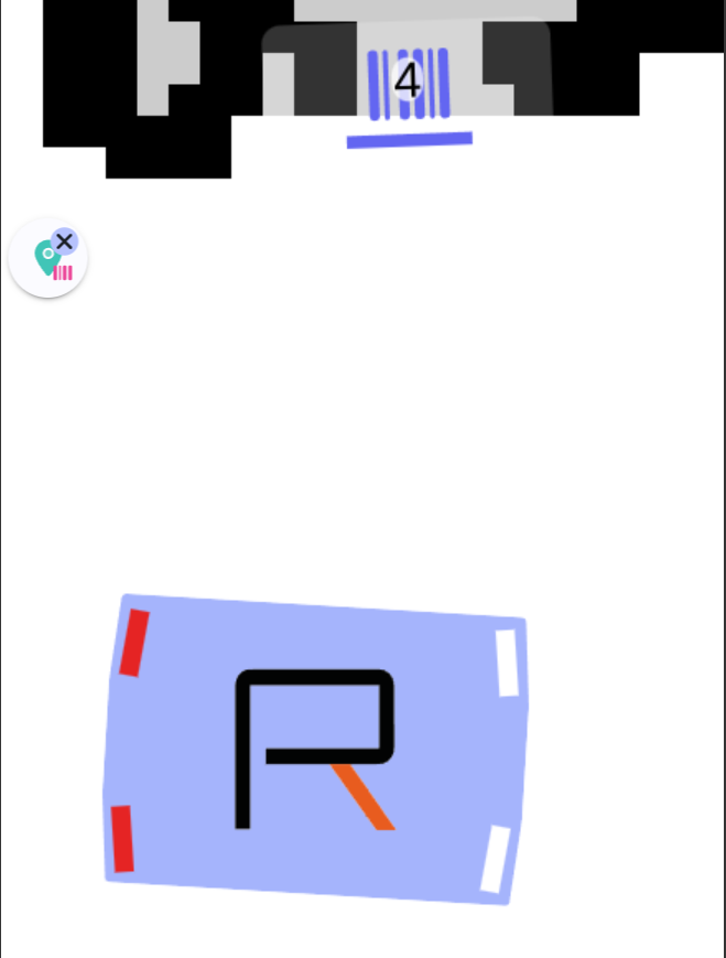
saved pose.The map marker with barcode icon initiates the process of adding a
docked pose.
Charging station
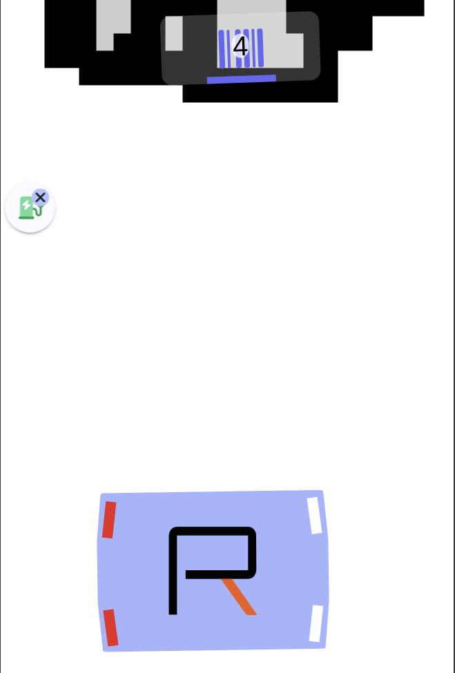
The charging station is a map element enabling the vehicle to charge itself by making contact with its dock and charging pins. The process of docking in order to make contact with its station is a special one, requiring precise guidance of the vehicle to the station marker, this special move starting at a certain distance from the station: the approach distance. Conversely, if the vehicle is docked, it must first undock before it can make autonomous movements. It will therefore have to reverse a distance called the docking distance.
On the map 🗺️, this element is represented by a gray solid rectangle with the dimensions of the station, a blue bar representing the station marker, and a rectangle footprint the size of the vehicle in green, with a charging station icon corresponding to the vehicle's docked pose.
If several charging stations are present, one must be set as the preferred charging station, allowing the vehicle to charge automatically at this one if the vehicle falls below its critical battery threshold.
Once the add process has started, the vehicle will scan the surrounding area. If it finds a marker, it will be displayed on the map with its detected ID, and the view will zoom in on the vehicle and markers found.
A click on a marker will complete the addition of the charging station and open directly its editing form so that you can modify the name, description or undock and approach distances, and define whether the station is the vehicle's preferred one.
The actions available via the menu for this item are deleting 🗑, opening the editing form ⚙️, and triggering a move to the charging station.
The list of editable fields in the charging station edit form is organized as follows:
General
Here you'll find the general parameters of the charging station:
UUID 🆔 :
UUID, the station ID within the map.
This field is not editable, as it is generated by the vehicle when a map containing the element is saved; when created, elements all have UUID -1.
Marker 🔢 :
Marker, the marker associated with thecharging station.
The marker is the visual identifier of the station on which the vehicle can be guided with great precision. This field is not editable.
Name 🪪 :
Name, the name of the station.
Naming particular charging stations may come in handy for future configurations.
Description 🗒️: A description of the
charging station.
Parameters
These parameters modify the charging station configuration.
Preferred charging station ⭐:
Preferred charging station, the vehicle's preferred charging station is the charging station to which the vehicle will automatically go if its battery falls below thecritical battery threshold. Checking a station will uncheck the others stations on the map, as the vehicle can only have one preferred station.
Checked or unchecked.
Undock distance 🔙 :
Undock distance, the undock distance is the distance the vehicle travels backwards when undocking.
Between 0.5 and 1 m, 0.5 by default.
Approach distance 🔜 :
Approach distance, the approach distance is the distance from the station at which the vehicle will start looking for the marker and will guide itself very precisely on it.
Between 0.5 and 1 m, 0.5 by default.
Note: For all editing forms, it is possible to show and hide certain settings sections, and save this visibility state via the small padlock 🔒. When opening a form, sections with values other than the default will automatically be opened (unless a save on close via padlock has been set) as well as all sections that have been saved in the open position previously. Handy for identifying which setting has been configured, or for configuring several elements of the same type in sequence, for example.
Saved pose
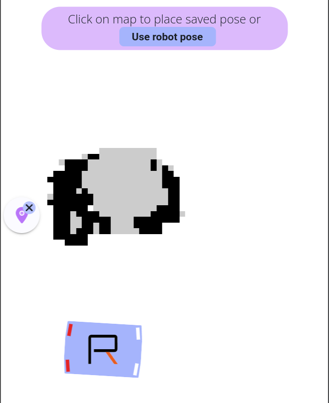
The saved pose is a map element that allows the vehicle to save a position in its map. It can then be used to trigger a move to it via a move command, a step in the autopilot sequence, or even via its module's mission.
On the map 🗺️, this element is represented by a rectangle footprint the size of the vehicle, in a customizable color, with a icon that can also be customized.
To add a saved pose, simply click at the desired position on the map to define the location, and the second click will define the element's orientation.
The Use robot pose button is available in the help at the top of the page, so simply move the vehicle to the desired position and use its current position to place the saved pose.
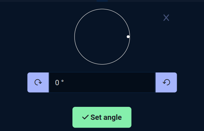
On a touch screen 📱, orientation is set via an angle selector. Once the creation process is complete, the editing form opens, allowing you to modify the name, description, icon and color, as well as setting the element's angle again.
The actions available via the menu for this element are delete 🗑, open the editing form ⚙️, saved pose clone process, translate process and trigger a move to the saved pose.
The list of editable fields in the saved pose edit form is organized as follows:
General
Here you'll find the general parameters of the saved pose:
UUID 🆔 :
UUID, the saved pose ID within the map.
This field is not editable, as it is generated by the vehicle when a map containing the element is saved; when created, elements all have UUID -1.
Name 🪪 :
Name, the name of the station.
Naming particular saved poses may come in handy for future configurations.
Description 🗒️: A description of the
saved pose.
Display
These parameters modify the display of the saved pose.
Color 🟦 :
Color, the color in which the saved pose will be drawn on the map.
A color selector appears to facilitate color selection.
Icon ❔ :
Icon, the icon to be drawn on the map.
An icon selector will appear to facilitate icon selection.
Orientation
Angle 🧭 : the orientation of the
saved pose.
The angle can be configured using the wheel and the two buttons which add or subtract 5 degrees.
Note: For all editing forms, it is possible to show and hide certain settings sections, and save this visibility state via the small padlock 🔒. When opening a form, sections with values other than the default will automatically be opened (unless a save on close via padlock has been set) as well as all sections that have been saved in the open position previously. Handy for identifying which setting has been configured, or for configuring several elements of the same type in sequence, for example.
Docked pose
The docked pose is a map element that allows the vehicle to position itself very precisely in relation to a marker (> 1 cm). It's the perfect fusion between a saved pose and a charging station on the marker side. Like the charging station, the vehicle will perform a docking process on the marker when moving to a docked pose.
This element is used if the vehicle needs to go very precisely, for example to the end of a conveyor to receive an object coming out of operation, in cases where the precision of autonomous navigation (> 5cm) would not be sufficient.
On the map 🗺️, this element is represented by a rectangular footprint the size of the vehicle in a customizable color, with a icon also customizable, and a blue bar representing the marker.
Once the add process has started, the vehicle will scan the surrounding area. If it finds a marker, it will be displayed on the map with its detected ID, and the view will zoom in on the vehicle and markers found.
A click on a marker will complete the addition of the docked pose and directly open its editing form, where you can modify its name, description, icon and color, or its undock and approach and safety disabling distances. The latter allows you to deactivate obstacle safety and dock close to an object normally considered an obstacle.
The actions available via this item's menu are delete 🗑, open the edit form ⚙️, and trigger a move to the docked pose.
The list of editable fields in the docked pose edit form is organized as follows:
General
Here you'll find the general parameters of the docked pose:
UUID 🆔 :
UUID, the docked pose's ID within the map.
This field is not editable, as it is generated by the vehicle when a map containing the element is saved; when created, elements all have UUID -1.
Marker 🔢 :
Marker, the marker associated with thedocked pose.
The marker is the visual identifier of the station on which the vehicle can be guided with great precision. This field is not editable.
Name 🪪 :
Name, the name of the docked pose.
Naming particular docked poses may come in handy for future configurations.
Description 🗒️: A description of the
docked pose.
Parameters
These parameters modify the docked pose configuration.
Undock distance 🔙 :
Undock distance, the Undock distance is the distance the vehicle travels backwards when undocking.
Between -2m and 2m, a negative value is equivalent to a forward distance.
Approach distance 🔜 :
Approach distance, the approach distance is the distance from the station at which the vehicle will start looking for the marker and will guide itself very precisely on it.
Between 0 and 2 m, 0.8 by default.
Disable safety distance ⚠ :
Disable safety distance, the disable safety distance is the distance from the position at which the vehicle will deactivate safety to come very close to an obstacle which is impossible under normal circumstances, equal to the approach distance which may be different for particular configurations.
Between 0 and 2 m.
Note: For all editing forms, it is possible to show and hide certain settings sections, and save this visibility state via the small padlock 🔒. When opening a form, sections with values other than the default will automatically be opened (unless a save on close via padlock has been set) as well as all sections that have been saved in the open position previously. Handy for identifying which setting has been configured, or for configuring several elements of the same type in sequence, for example.
Configuration menu
This menu lets you configure the vehicle's movement and other behavior on the map:
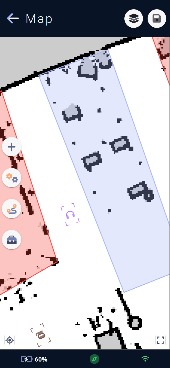
By adding
custom areas, represented by the blue polygon icon. Clicking on this button will start the process of adding a area.By adding
forbidden areas, represented by the red polygon icon with the ⛔ forbidden icon. Clicking on this button will start the process of adding a area.By configuring
traffic routesvia the road and padlock icon 🔒. A click on this button will open the routes menu.By configuring the vehicle's global behavior on the map via the map icon 🗺️. Clicking this button will open the map behavior editing form.
Custom area
The custom area is a map element that lets you configure special behaviors ⚙️ of the vehicle when inside it, but also when entering or leaving it.
On the map 🗺️, this element is represented by a polygon of configurable shape via its edges, in a customizable color.
To add a custom area, simply click on the desired position on the map to create the first edge of the polygon, and each click will add a new edge.
To complete the polygon, simply click on the first point previously drawn.
Note : the polygon must have at least 3 edges.
Once the creation process is complete, the edit form for the behavior associated with the area opens.
A custom area can influence vehicle behavior in a number of ways.
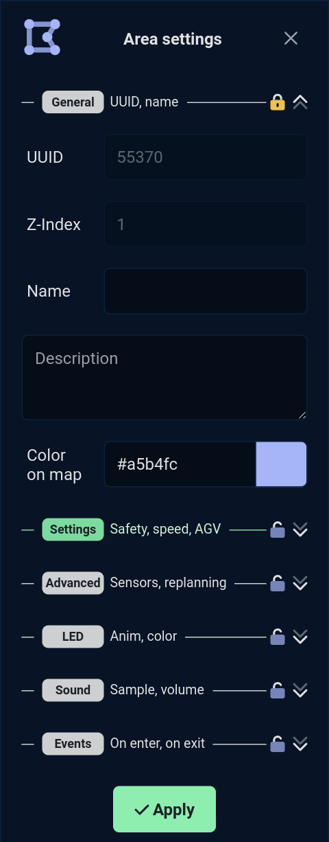
The list of editable fields in the custom area edit form is organized as follows :
General
Here you'll find the general parameters of the custom area:
UUID 🆔 :
UUID, the area ID within the map.
This field is not editable, as it is generated by the vehicle when a map containing the element is saved; when created, elements all have UUID -1.
Name 🪪 :
Name, the custom area name.
Naming particular areas may come in handy for future configurations.
Description 🗒️: A description of the area.
Color 🟦 : The color in which the area will be drawn on the map.
A color selector will appear to facilitate color selection.
Parameters
These parameters modify the vehicle's behavior.
Maximum speed 🚗 :
Max speed, the maximum speed of the vehicle moving in the area. This can be useful for reducing speed in a dense area or increasing it in a lightly trafficked area.
Between 0.1 and 1.0 m/s, by default the vehicle travels at 0.5m/s.
Safety margins ↔️ :
Safety margin, the distances at which the vehicle avoids approaching obstacles. This can be useful when the vehicle has to pass through restricted spaces such as a narrow corridor or a door.
Between -0.15 and 0.8 m, a negative value will reduce the default safety margins.
AGV mode 🛤️ :
AGV mode, the vehicle mode with constrained guidance. By default, the vehicle is allowed to deviate from its initial trajectory to avoid an obstacle and continue its progress. AGV mode prohibits the vehicle from deviate from its trajectory, and it will stop in the event of an obstacle and drive off once the obstacle has disappeared.
On or off.
Advanced settings
These advanced parameters allow further modification of the vehicle's behavior. Some have the potential to modify trajectory planning or safety, and should be used with caution.
Replanning timeout ⏱️ :
Replanning timeout, the replanning timeout. This is the time in seconds before the vehicle can re-plan a trajectory towards its goal. During a journey, the vehicle may encounter an obstacle that it cannot avoid or bypass. It will then replan to see if there is another way to reach its goal despite the obstacle, and this parameter influences the time within which it decides to replan.
Between 0 and 60 seconds.
Minimum obstacle height ↕️ :
Min obstacle height, the minimum obstacle height. This is the minimum height at which the vehicle will consider a detection to be an obstacle when planning its trajectory.
Between 0 and 0.2m or 20cm.
3D camera filter 📷 :
3D camera safety, the 3D camera safety filter. This is a filter for reducing the safety of 3D cameras if the proportion of environment-related false positives is too high.❗A value below 100 has a direct impact on vehicle safety, which will ignore a greater or lesser proportion of obstacles seen by the vehicle's cameras. USE WITH CAUTION ⚠️.
The application uses a slider with 4 available values to set this parameter:
0 No protection
70 Low protection
85 Medium protection
100 Total protection
Between 0 and 100, default 100.
Airplane mode ✈ :
No connection in area, the no connection mode. Used to indicate to the vehicle that this area has no connection whatsoever. This can be useful if the vehicle module needs to send information via an external network. The vehicle can then find out if it is in an area covered by the network, or search for one in its map using this parameter.
Activated or not, to be coupled with the card's general no connection mode.
Ultrasonic sensors 🔊 :
US sensors, the disabling of ultrasonic sensors. Allows you to tell the vehicle not to take into account feedback from its ultrasonic sensors in this area. Can be useful if an area is subject to ultrasonic disturbance.❗Disabling ultrasonics has a direct impact on the safety of the vehicle, which will potentially ignore obstacles only detected by the vehicle's ultrasonic sensors. USE WITH CAUTION ⚠️.
On or off.
LED
Allows you to set the animation and color of the vehicle's LEDs while in the custom area.
LED animation 🚥 :
LED Anim, the animation of the vehicle's LEDs.
If no animation is selected, the next LED parameters will be hidden.
LED Color 🟦 :
LED Color, the color of the LEDs.
Some animations, such as the French flag, do not require a color setting, and this drop-down menu will be hidden if one of these animations is selected.
Sound
Allows you to set the sound played in a loop by the vehicle while it is in the custom area.
Sound 🎶 :
Sound, the jingle sound to be played among all those available on the vehicle.
If no jingle is selected, the next sound settings will be hidden.
Volume 🔊 :
Volume, the volume at which to play the jingle while the vehicle is present in the area.
The application uses a volume knob with 3 available values to set this parameter:
LowLow volume 10MediumMedium volume 55HighHigh volume 100
Between 0 and 100, by default 100, will then be limited by the value of the vehicle's sound scenario Area.
Loop delay ⌛ :
Loop delay, the wait in seconds between two jingles played by the vehicle as long as it is in the area.
0 or more seconds, default 0.
Events
Allows you to set the sound played and LEDs displayed by the vehicle when it enters or exits the custom area.
The two events for entering the On enter area and exiting the On exit area can be set as follows:
LEDs
LED animation 🚥 :
LED Anim, the animation of LEDs from among those available on the vehicle.
If no animation is selected, the next LED parameters will be hidden.
LED Color 🟦 :
LED Color, the color of the LEDs.
Some animations, such as the French flag, do not require a color setting, and this drop-down menu will be hidden if one of these animations is selected.
LED duration ⌛ :
LED duration, the duration for which the LEDs will be displayed once the event has been triggered.
1 or more seconds, default 5.
Sound
Sound 🎶:
Sound, the jingle sound to be played among all those available on the vehicle.
If no jingle is selected, the next sound parameters will be hidden.
Loop count ⌛:
Loop count, the number of times the jingle will be played.
A value of less than 2 on this parameter will logically render the loop delay parameter useless.
Volume 🔊 :
Volume, the volume at which to play the jingle once the event has been triggered.
The application uses a volume knob with 3 available values to set this parameter:
LowLow volume 10MediumMedium volume 55HighHigh volume 100
Between 0 and 100, by default 100, will then be limited by the value of the vehicle's sound scenario Area.
Loop delay ⌛ :
Loop delayThe wait in seconds between two jingles played by the vehicle tune once the event has been triggered.
0 or more seconds, default 0.
Note: For all editing forms, it is possible to show and hide certain settings sections, and save this visibility state via the small padlock 🔒. When opening a form, sections with values other than the default will automatically be opened (unless a save on close via padlock has been set) as well as all sections that have been saved in the open position previously. Handy for identifying which setting has been configured, or for configuring several elements of the same type in sequence, for example.
Forbidden area
The forbidden area is a map element used to indicate areas forbidden to navigation ⛔ to the vehicle. The vehicle will not be able to cross or exit these areas if it finds itself in them via physical displacement or via Teleop joystick in free mode.
It will refuse any orders that would force it to encounter it in its trajectory.
⚠️ Please note that adding forbidden areas is a critical operation for the vehicle ⚠️
Certain specific areas must be "protected" by a forbidden area (e.g. Escalator...) and the operator 👷🏽♂️ modifying these areas on the map must be trained by the Team Rob'Occ or equivalent.
On the map 🗺️, this element is represented by a polygon of configurable shape via its edges, in a red color 🟥.
To add a forbidden area, simply click on the desired position on the map to create the first edge of the polygon, and each click will add a new edge.
To complete the polygon, simply click on the first point previously drawn.
Note : the polygon must have at least 3 edges.
Once the creation process has been completed, it is possible to recreate another polygon, thus creating the forbidden area in the chain.
An edit form is available for the forbidden zone, allowing you to set a name and description.
Traffic routes
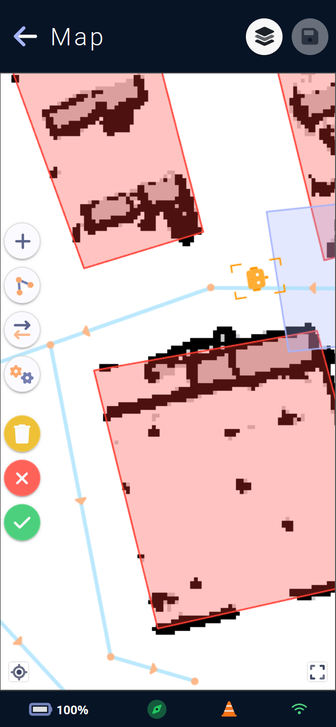
Traffic routes indicate to the vehicle how to move in its active map. They can be used to define one-way traffic zones, or to specify how a vehicle should run along a wall in one direction, then along the other wall in the opposite direction, for example.
On the map, roads are green if they are configured as two-way, blue if they are one-way. The triangles show in which direction they are set.
You can select a route by clicking on it, and a button appears for deleting the route. Route selection is only possible if the route menu is open and no route operating mode (adding, editing...) is in progress.
The route menu is divided as follows:
The plus icon ➕ starts the process of creating new routes, the first click sets the origin of the route, subsequent clicks steps on that route, to end the creation simply either re-click the last point, or re-click the plus icon.
The drawing icon lets you modify routes already created by moving a vertex, or by adding a step to a route by clicking directly on the route segment to add a point. Clicking this button again exits the route editing mode.
The double-arrow icon lets you change the direction of a route by clicking on all routes requiring a change of route. The route will then alternate between straight, reverse and double direction. Clicking this button again exits the route direction change mode.
The double gear icon ⚙️ opens the route parameters editing form.
The yellow trash can icon 🗑️ is used to delete all routes and return to a map without any routes.
The red cross icon ❌ cancels route modifications made since last opening the route menu.
The green tick icon ✅ saves route modifications made since last opening the route menu.
Note : Changes will only be applied the next time the map is saved.
Creating and editing routes
When creating a new vertex or moving an existing one, if its location is validated on another vertex already present, the moved or created vertex is merged with the existing vertex.
Route parameters
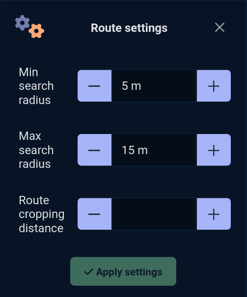
Three parameters influence vehicle behavior:
Min search radius:
Min search radius, the minimum distance at which the vehicle searches for a route from its position.
Between 1 and 20 meters, default 5.
Max search radius:
Max search radius, the maximum distance the vehicle will search for a road from its position.
Between 1 and 100 meters, default 15.
Cropping distance:
Route cropping distance, the ignored distance cropped by the vehicle when usingtraffic routes, to facilitate navigation.
Between 0 and 300 centimetres, default 0.
Road obstacles
When configuring traffic routes, it is possible that some routes are too close to a wall, a forbidden area or a custom area with safety margin settings that are too restrictive.
The vehicle will then deem some of these roads unusable and create a road obstacle.
On the map, these obstacles are easily identified by an exclamation mark❗in a red circle.
It is then necessary to correct the problem, so that the vehicle can use its traffic roads without problem.
Note : the vehicle can only detect and remove road obstacles if autonomous navigation is activated.
Map settings
Global map settings allow you to configure special ⚙️ vehicle behaviors across the entire map without having to create a custom area across the map extent.
Coupled with custom area, the vehicle's behavior can be modified across the entire map, and if it enters a custom area, a new value can be applied to one of the fields.
This allows you, for example, to tell the vehicle to go at a maximum speed of 0.7m/s on the map, and to reduce it again in specific (densely populated) areas.
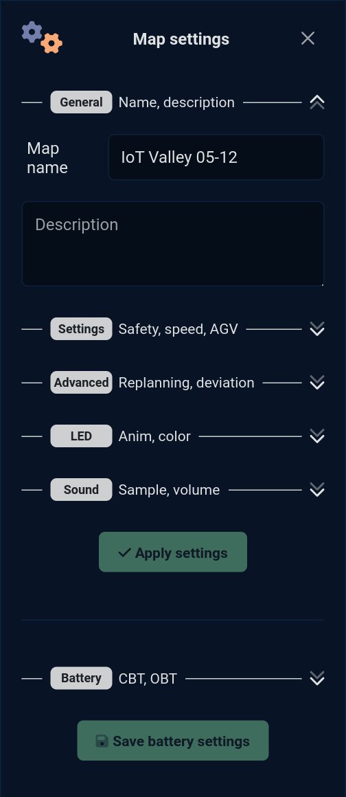
This form can also be used to modify the name and description of the active map.
The list of editable fields on the global map editing form is organized as follows:
General
Here you'll find the general parameters of the active map:
Name 🪪 :
Name, the name of the active map.
By default, the map will have the same name as the site in which it was created.
Description 🗒️ : A description of the active map.
Parameters
These parameters modify the vehicle's behavior.
Maximum speed 🚗 :
Max speed, the maximum speed of the vehicle, applied to the entire map outside acustom areawhere the maximum speed would have been configured with a different value.
Between 0.1 and 1.0 m/s, by default the vehicle travels at 0.5m/s.
Safety margins ↔️ :
Safety margin, the distances at which the vehicle avoids approaching obstacles, applied to the entire map outside acustom areaor the safety margins would have been configured with a different value.
Between -0.15 and 0.8 m, a negative value will reduce the default safety margins.
AGV mode 🛤️ :
AGV mode, vehicle mode with constrained guidance. By default, the vehicle allows itself to deviate from its initial trajectory to avoid an obstacle and continue its progress. AGV mode prohibits the vehicle from deviate from its trajectory, and it will stop in the event of an obstacle and drive away once the obstacle has disappeared..
On or off.
Preferred charging station 🔌 :
Preferred charging station, the vehicle's preferred charging station, the station to which the vehicle will automatically go if it falls below itscritical battery threshold.
UUID of a station on the map.
Advanced settings
These advanced parameters allow further modification of vehicle behavior. Some have the potential to modify trajectory planning or safety, and should be used with caution.
Replanning timeout ⏱️ :
Replanning timeout, the replanning timeout. This is the time in seconds before the vehicle can re-plan a trajectory towards its goal. During a journey, the vehicle may encounter an obstacle that it cannot avoid or bypass, so it will replan to see if there is another way to reach its goal despite the obstacle. This parameter influences the time within which it decides to replan, applied to the entire map outside acustom areawhere the planning timeout would have been configured with a different value.Minimum obstacle height ↕️ :
Min obstacle height, the minimum obstacle height. This is the minimum height at which the vehicle will consider a detection as an obstacle in its trajectory planning, applied to the entire map outside acustom areawhere the minimum obstacle height would have been configured with a different value.
Between 0 and 0.2m (20cm).
Airplane mode ✈ :
No connection in area, the no connection mode. Indicates to the vehicle that this map has or has not connection of any kind. This can be useful if the vehicle module needs to send information via an external network. The vehicle can then find out if it is in an area covered by the network, or search for one in its map via this parameter.
Activated or not, to be coupled with the connectionless mode of the map's custom areas.
LED
Allows you to set the animation and color of the vehicle's LEDs applied to the entire map outside a custom area where the LEDs have been configured with different values.
LED animation 🚥 :
LED Anim, the animation of the LEDs among all those available on the vehicle.
If no animation is selected, the next LED parameters will be hidden.
LED Color 🟦 :
LED Color, the color of the LEDs.
Some animations, such as the French flag, do not require a color setting, and this drop-down menu will be hidden if one of these animations is selected.
Sound
Allows you to set the sound played in a loop by the vehicle applied to the entire map outside a custom area where the sound would have been configured with different values.
Sound 🎶 :
Sound, the jingle sound to be played among all those available on the vehicle.
If no jingle is selected, the next sound settings will be hidden.
Volume 🔊 :
Volume, the volume at which to play the jingle.
The application uses a volume knob with 3 available values to set this parameter:
LowLow volume 10MediumMedium volume 55HighHigh volume 100
Between 0 and 100, by default 100, will then be limited by the value of the vehicle's sound scenario Area.
Loop delay ⌛ :
Loop delay, the wait in seconds between two jingles played by the vehicle as long as it is in the area.
0 or more seconds, default 0.
Battery
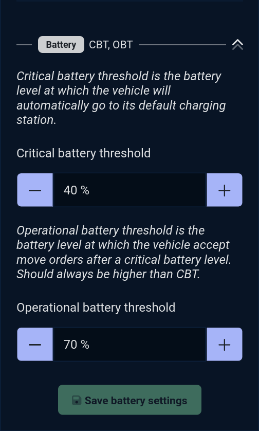
Sets the two battery values linked to the active map.
CBT 🪫 :
Critical battery threshold. This is the battery level at which the vehicle will automatically go to its default charging station to recharge. Depending on the size of the map, this threshold can be set to ensure that the vehicle can reach its station no matter where on the map this threshold is reached.OBT 🔋 :
Operational battery threshold. This is the battery level at which the vehicle accepts travel commands after a battery has reached the critical battery threshold. It must always be higher than the CBT. This threshold can be more or less distant from the CBT to guarantee the vehicle a more or less durable use after having reached a critical battery threshold.
Note : Some modules charge automatically the vehicle, i.e. send it to charge if no mission is in progress, leaving it to recharge throughout use, and these two thresholds can be unused.
Move menu
This menu is used to move the vehicle.
The target icon 🎯 sends the vehicle to the position clicked on the map, orientation is set via an angle selector.
The joystick icon 🕹️ opens the map's virtual joystick (see #Move).
The ➡️ arrow icon is used to draw a navigation segment which will be carried out directly by the vehicle.
It will move in autonomous navigation until the start of the segment, and then follow a fully straight path until the end of the segment. A straight-line travel behavior where the vehicle does not deviate from its line (it will stop in the event of an obstacle but will not go around it) can be useful for certain use cases.
The electrical plug icon 🔌 sends the vehicle to its preferred charging station.
Toolbox menu
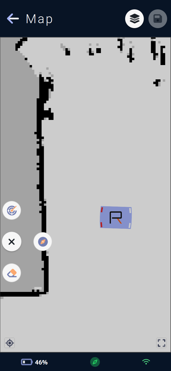
This menu allows you to use tools available for the map or for the vehicle.
The radar icon 📡 asks the vehicle to perform a
relocation: the vehicle will scan the surroundings and, if it finds a marker in memory in its map, it will reposition itself perfectly in relation to this marker.
This process also initiates the vehicle's autonomous navigation if it has not already been started.
The compass icon 🧭 allows you to manually locate the vehicle by clicking on the map at the point where the vehicle is physically located. The vehicle will then believe itself to be in that position. Once located, the vehicle will recall itself according to the elements it sees and the position at which it was manually located.
⚠️ Warning: manual localization is a critical operation for vehicles ⚠️
The vehicle could get totally lost and ignore forbiddens areas for example if its location is not good and the 👷🏽♂️ operator using this process must be trained by the Rob'Occ team or equivalent.
This process also launches the vehicle's autonomous navigation if it has not yet been started.
The eraser icon 🧽 opens the eraser menu, allowing you to erase impure leftovers of cartography directly from the map, or remove obstacles that are no longer physically present. Erasing can improve vehicle localization and autonomous navigation.
⚠️ Warning, erasing the map is a critical vehicle operation ⚠️
Menu Eraser
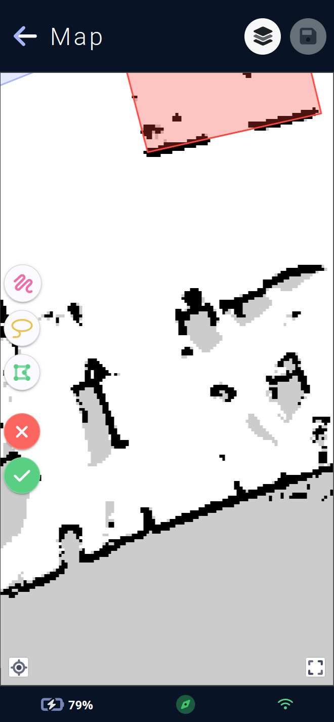
The eraser menu lets you add areas to be erased in three different ways:
The freehand drawing icon lets you create erasers freehand. This will draw as long as the mouse, or finger if accessing the app via a phone 📱 or tablet, remains pressed down on the map.
The lasso icon lets you create erasers by surrounding the area to be erased. Once the mouse (or finger) is released, a polygon will form inside the area drawn on the map.
The polygon icon can be used to create erasers in the same way as
forbiddens areasorcustoms areas. Simply click on the desired position on the map to create the first edge of the polygon, and each click will add a new edge. To terminate the polygon, simply click on the first point previously drawn.The red button with a cross ❌ cancels all unsaved eraser modifications and allows you to return to an eraser-free map (all erasers visible on screen will be deleted).
The green button with a checkmark ✔️ allows the vehicle to delete areas drawn on its map. This allows it to remove elements from its trajectory planning, but can also affect its location, as there may be less correspondence between what it sees and what it knows is normally present on the map.
These last two buttons will require confirmation before deleting or applying the erasers present on the map.
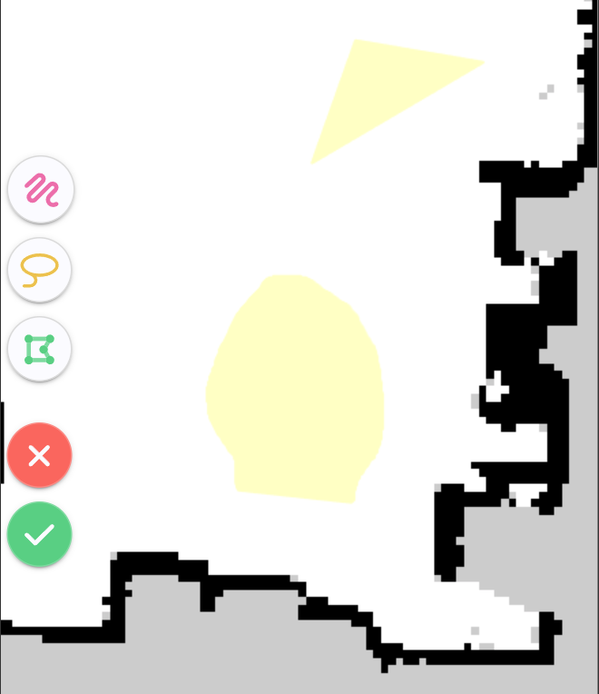
Once the erasers have been drawn, they are visible in yellow on the map and represent the areas that will be cleaned by the vehicle. They can be removed by selecting them on the map and using the trash can icon 🗑️.
Selection is possible only if no creation mode is currently selected. The current creation mode is indicated in yellow by its button on the menu, and can be cancelled by clicking on the same button again.
Menu layers
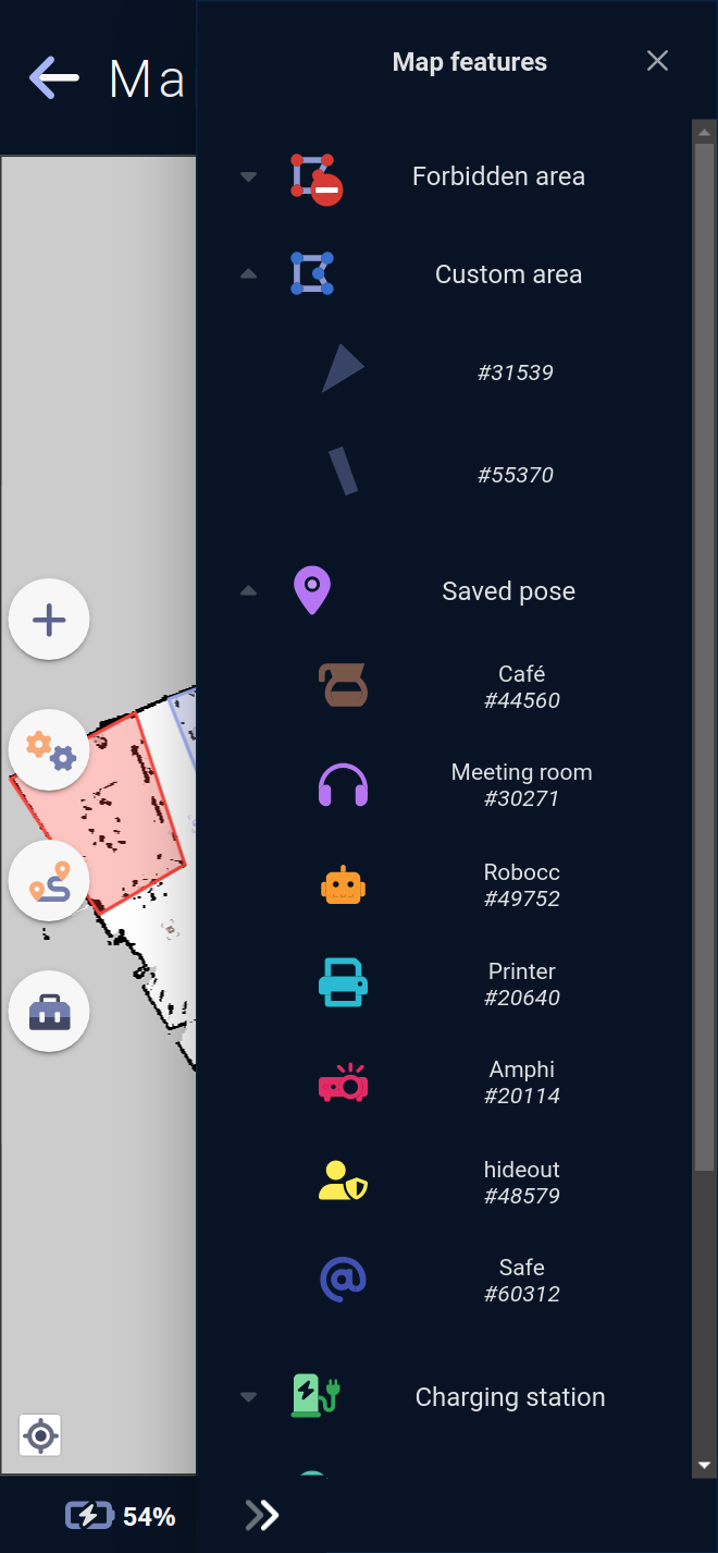
This menu allows you to hide or show certain layers or elements on the map, as well as to select an element on the map.
A click on the icon hides or shows the group of elements on the map.
Lists can be opened to list elements.
In the case of an element with an icon and a customizable color (saved pose, docked pose, etc.), the element will have the corresponding icon in its color. In the case of a customizable zone or forbidden zone, a drawing of the zone's shape will be present.
Clicking on an element icon hides or displays the element, while clicking on its name selects it.
When selected, the map view will be centered on the newly selected element.
Note: On PCs, for ease of use, the element is preselected by hovering the cursor over it.